
Industry trends
Focus on semiconductor electrical performance testing
location:Home > News > Industry trends
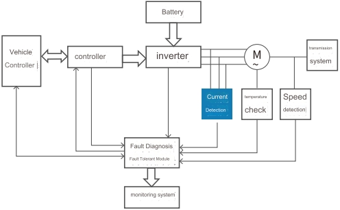
Hall current sensors are widely used in aerospace, power supply monitoring, aircraft status monitoring, variable speed drive equipment, welding equipment power supplies, new energy vehicle battery management systems and other fields. They have an important position and practical value in the field of current detection. They are also used in electric drives. The system is called the power "heart" of new energy vehicles. Therefore, the reliability of the Hall current sensor determines the technical level of the electric drive system.
With the development and progress of science and technology, as well as the upgrading and iteration of semiconductor technology and preparation processes, high-power semiconductor components have developed extremely rapidly and are widely used in fields such as current monitoring, frequency conversion control testing, AC and DC power supplies, power inverters, and electronic switches. . For Hall current sensors, the future will develop in the direction of larger current detection range, faster response speed, better anti-interference ability, wider operating temperature range, and lower power consumption.
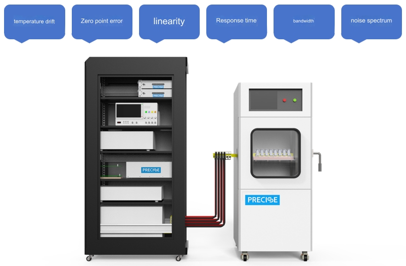
During the development and use of Hall current sensors, reliability testing of the device is required, which mainly includes static test items such as zero point, linearity, error, etc., dynamic test items such as bandwidth, response time, noise, etc., as well as temperature drift test, etc. The testing of these parameters is of great significance for judging whether the performance of the Hall current sensor is stable and reliable, analyzing its working mechanism, verifying its working performance, and guiding device selection and use.
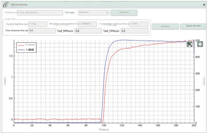
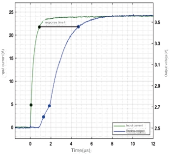
Response time refers to the delay between the rise time of the sensor output signal and the rise time of the actual signal. This delay is called the response time, which is the time difference between the output signal (secondary current IS) and the input signal (primary current IP).
Under standard power supply and ambient temperature conditions, test the output response time of the current sensor at the rated primary current value. For closed-loop Hall current sensors, the response time is generally at the μs level. Therefore, this requires the primary current output source used for testing to have fast current output capability.
One PRECISE HCPL100 high-current pulse power supply and two S300 high-precision digital source measure meters were used for actual measurement. The entire test process is very simple to use. According to the difference in current/voltage output of the Hall current sensor, connect the device according to the following test connection line By connecting with the source measure unit, the response time test of the Hall current sensor can be completed in a very short time.
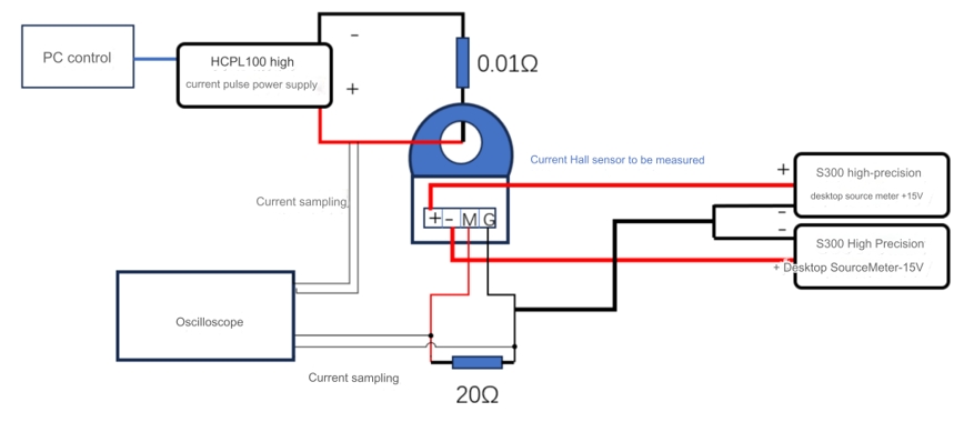
Current output type Hall current sensor test connection circuit diagram
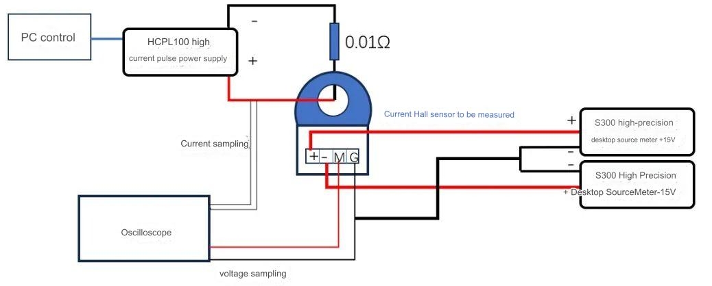
Voltage output type Hall current sensor test connection circuit diagram
In addition, when building the circuit, the probes used to test the primary current signal and the current sensor output signal must be connected to the oscilloscope to ensure synchronous signal collection.
