

Diode Characteristics Test I-V C-V
Focus on semiconductor electrical performance testing
Position:Home > Solutions > Semiconductor discrete devices
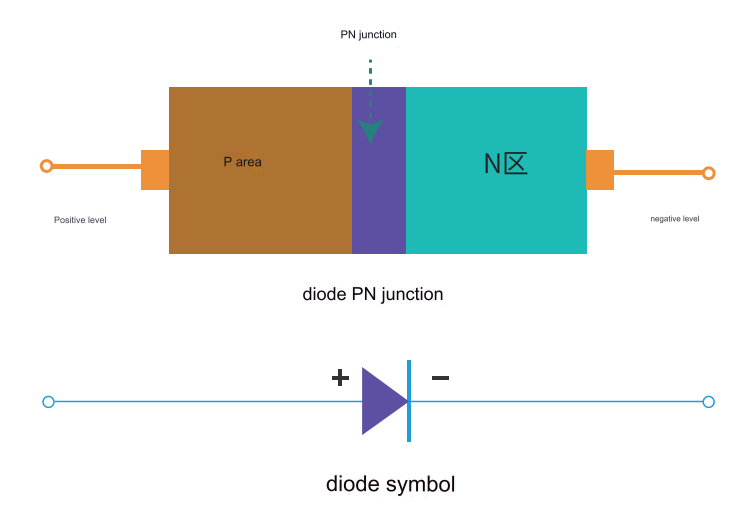
A diode is a unidirectional conductive component made of semiconductor materials.The product structure is generally a single PN junction structure, which only allows current to flow in one direction.Diodes are widely used in rectification,voltage stabilization,protection and other circuits,and are one of the most widely used electronic components in electronic engineering.
Diode Characteristics Test is to apply voltage or current to Diode,and then test its response to excitation.Usually,Diode Characteristics Test requires several instruments to complete,such as digital multimeter,voltage source,current source, etc.However,a system composed of several instruments needs to be programmed,synchronized, connected,measured and analyzed separately.The process is complex, time-consuming,and takes up too much test bench space;Complicated mutual trigger operations have disadvantages such as greater uncertainty and slower bus transmission speed.
Therefore,in order to quickly and accurately obtain Diode test data such as current-voltage (I-V), capacitance-voltage (C-V) characteristic curves, etc.One of the best tools for implementing Diode Characteristics Test is a source measure unit (SMU).The Source measure Meter can be used as a stand-alone constant voltage or constant current source,voltmeter,ammeter,and ohmmeter,and can also be used as a precision electronic load.Its high-performance architecture also allows it to be used as a pulse generator,waveform generator,and automatic Current-voltage (I-V) characteristic analysis system supports four-quadrant operation.
The diode iv characteristic is one of the main parameters to characterize the performance of the PN junction of a semiconductor diode. The diode iv characteristics mainly refers to the forward characteristic and the reverse characteristic.
When a forward voltage is applied to both ends of the diode,in the initial part of the forward characteristic,the forward voltage is very small and the forward current is almost zero.This section is called the dead zone. The forward voltage that cannot make the diode conduction is called the dead zone voltage.When the forward voltage is greater than the dead-zone voltage,the diode is forward-conducting, and the current rises rapidly as the voltage increases.In the current range of normal use,the terminal voltage of the diode remains almost unchanged when it is turned on,and this voltage is called the forward voltage of the diode.
When the reverse voltage is applied,if the voltage does not exceed a certain range,the reverse current is very small,and the diode is in a cut-off state.This current is called reverse saturation current or leakage current.When the applied reverse voltage exceeds a certain value,the reverse current will suddenly increase,and this phenomenon is called electrical breakdown.The critical voltage that causes electrical breakdown is called the diode reverse breakdown voltage.
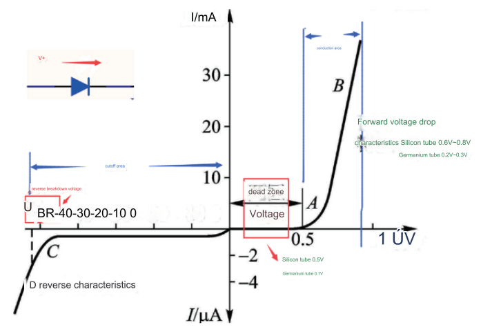
The diode characteristics that characterize the performance and application range of diodes mainly include parameters such as forward voltage drop (VF), reverse leakage current (IR) and reverse breakdown voltage (VR).
Under the specified forward current,the forward voltage drop of the diode is the lowest forward voltage that the diode can conduct.The forward voltage drop of low-current silicon diodes is about 0.6-0.8 V at medium current levels;the forward voltage drop of germanium diodes is about 0.2-0.3 V;the forward voltage drop of high-power silicon diodes often reaches 1V.When testing,it is necessary to select different test instruments according to the size of the working current of the diode: when the working current is less than 1A,use the S series source measure meter for measurement;when the current is between 1 and 10A, it is recommended to use the P series pulse source measure unit;HCP series high current desktop pulse source is recommended for 10~100A;HCPL100 high current pulse power supply is recommended for above 100A.
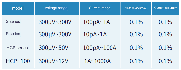
Depending on the material and structure of the diode,the breakdown voltage is also different.If it is lower than 300V,it is recommended to use the S series desktop source measure unit,and if it is higher than 300V it is recommended to use the E series high-voltage source measurement unit.

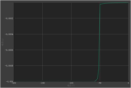
During high current testing,the resistance of the test lead cannot be ignored, and the four-wire measurement mode is required to eliminate the influence of the lead resistance.All PRECISE source measure meters support the four-wire measurement mode.
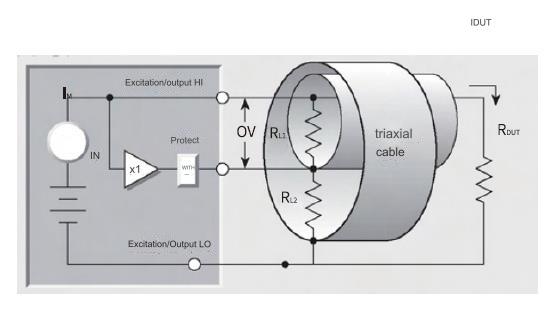
When measuring low-level currents (<1µA),triax connectors and triax cables can be used.The triaxial cable consists of an inner core (main, the corresponding connector is the central contact),a protective layer (the corresponding connector is the middle cylindrical contact),and an outer sheath shielding layer.In the test circuit connected to the protection terminal of the source measure meter,since the protective layer and the inner core of the triax are equipotential,there will be no leakage current,which can improve the low current test accuracy.
In addition to I-V test, C-V test is also required for diode parameter characterization. The C-V measurement method can obtain characteristics such as diode doping concentration and defects; the diode C-V test solution consists of S series source measuring unit, LCR, test fixture box and host computer software.