

Use the Precise high current pulse source measure meter to complete the current sensor parameter test
Simplify sensor characteristics analysis, improve test efficiency solution enquiry
overview
The current sensor is a detection device that can sense the information of the measured current, and can transform the detected information into a standard electrical signal or other forms of information output according to certain rules, so as to meet the requirements of information transmission, processing, Storage, display, recording and control requirements. According to different measurement principles, current sensors can be mainly divided into: shunts, electromagnetic current sensors, electronic current sensors, TMR magnetic sensors, etc. Electronic current sensors include Hall current sensors, Rogowski current sensors, and variable frequency power sensors (usable for voltage, current, and power measurement) for variable frequency electrical measurement.
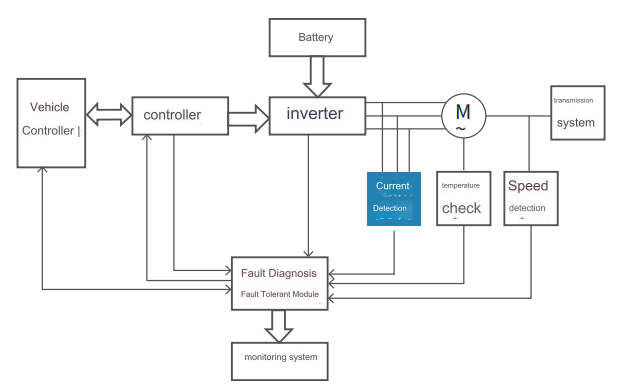
Hall current sensor test
During the development and use of the Hall current sensor, the measurement of the response speed, linearity, and accuracy of the device is particularly important, which is of great significance to ensure the stable performance and reliable operation of the device, and to guide the selection and use of the device.
Linearity: The degree to which the output signal (secondary side current IS) is proportional to the input signal (primary side current IP) within the measurement range. For example, when the current is 40A, the output is 4V (or 50mA), and when the current is 20A, the output should be 2V (or 25mA). These are ideal values, and the actual output will have some deviations. The ratio of the deviation value to the ideal value is the linearity error. , the smaller the linear error value, the higher the detection accuracy, and the linearity of the current sensor is represented by the linear error.
Accuracy: The degree of deviation between the current sensor test value and the true value. The accuracy test of the current sensor depends on the performance of the device itself, and also has a great relationship with the accuracy of the standard test source used for calibration. Response time: There will be a delay between the rise time of the output signal and the rise time of the actual signal. This delay is called the response time, which is the time difference between the output signal (secondary side current IS) and the input signal (primary side current IP).
Temperature drift: When the working environment temperature of the current sensor changes, its output test value will be deviated accordingly. Measuring the stable output performance of the device at different temperatures has important guiding significance for use.
Response bandwidth: Under a specified amplitude input signal and a specific frequency, the output amplitude of the current sensor will attenuate to a specified proportional value, generally -1dB or -3dB. Generally speaking, the output response signal of the current sensor will attenuate with the increase of the primary current value and frequency.
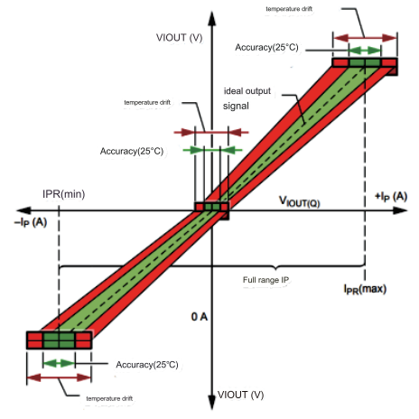
Linearity Test Curve
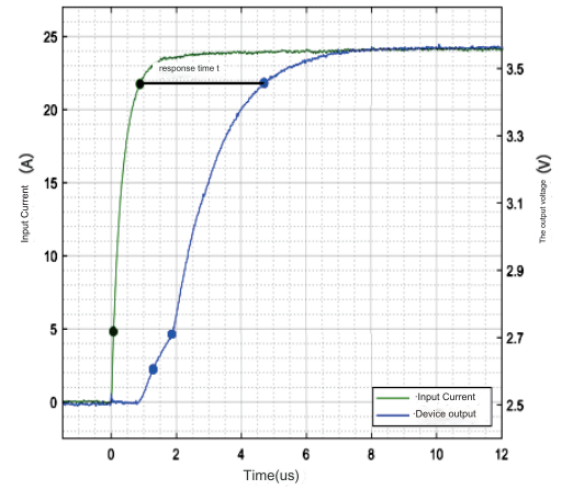
Response time test curve
Precise Current Sensor Test Solution
CTMS Current Sensor Test System
Precise CTMS current sensor test system can be used to accurately measure the static and dynamic parameters of various current sensors (Hall current sensors, Rogowski coils, Pearson coils, etc.), and the current of a single high-current source can be as high as 1000A. Test parameters include: DC parameters such as temperature drift, zero point error, linearity, etc., and AC parameters such as response time, bandwidth, noise spectrum, etc. The CTMS current sensor test system generally includes: test equipment, host computer control system, test fixture, etc. The test equipment mainly includes DC high current source equipment, step pulse current source equipment, broadband high current source equipment, spectrum analyzer, oscilloscope, current direction switching device, ambient temperature simulation device, sensor power supply device, data acquisition device, etc. The upper computer control system mainly includes functional modules such as instrument control, automatic data collection, automatic storage, and data generation, as well as the design of the test interface.
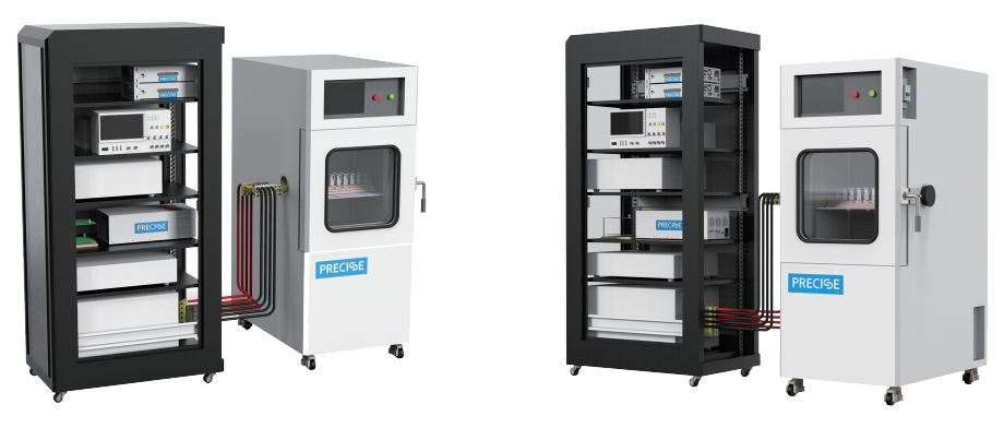
Precise CTMS Current Sensor Test System
Zero point, sensitivity, linearity test
Under the standard power supply and ambient temperature conditions, refer to the range of the current sensor, and measure the output signal of the sensor according to the 10% step as a test point (or according to the current step specified by the customer).
Response time test
Under standard power supply and ambient temperature conditions, the output response time of the current sensor at the rated primary current value. For closed-loop Hall current sensors, the response time is generally in the μs level. Therefore, this requires the primary current output source used for testing to have fast current output capability. In addition, when building the circuit, the probes used to test the primary current signal and the output signal of the current sensor must be connected to the oscilloscope to ensure that the signals are collected in the same layout.
Temperature Drift Test
Output signal characteristic curve at temperature. Under standard power supply conditions, test the output signal characteristic curve of the current sensor at different ambient temperatures.
Frequency Bandwidth Test
Under the standard power supply and ambient temperature conditions, test the current sensor output signal response curve of the current sensor in different frequency bandwidth sine waves.
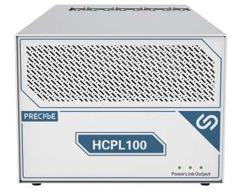
High current pulse power supply HCPL100
Precise high-current pulse power supply HCPL100 is a dedicated test power supply with high current, high precision and wide measurement range built by Wuhan Precise. It has the characteristics of large output current (1000A), steep pulse edge (15μS), and supports output polarity switching.
Fixture
For different packaging forms, different fixtures are designed to meet the test of conventional packaging, such as QFN, SOIC, SOICW, PFF, PSF and core type.
